ข้ามไปที่เนื้อหา
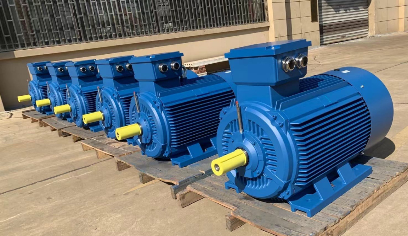
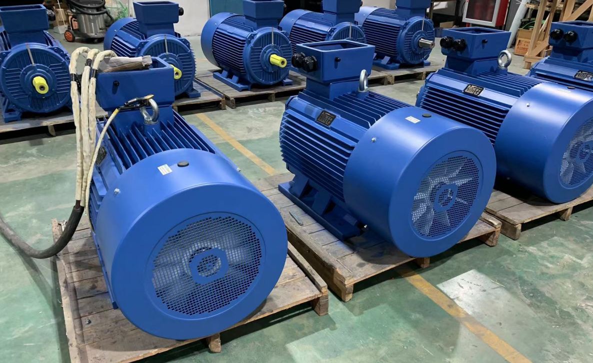
Nearly half of the world's power consumption is consumed by electric motors, so the high efficiency of electric motors is said to be the most effective measure in solving the world's energy problems.
Types of มอเตอร์ไฟฟ้า
In general, it refers to the transformation of the force generated by the flow of current in a magnetic field into a rotary action, and in a broad range, it also includes linear action.
Depending on the type of power supply used to drive the motor, there are DC motors and AC electric motors.
และตามหลักการหมุนมอเตอร์มันสามารถแบ่งออกเป็นหมวดหมู่ต่อไปนี้โดยประมาณ (ยกเว้นมอเตอร์พิเศษ)
มอเตอร์ DC Electric /DC (กระแสไฟฟ้าโดยตรง)
มอเตอร์แปรง
มอเตอร์แปรงที่ใช้กันอย่างแพร่หลายโดยทั่วไปเรียกว่ามอเตอร์ไฟฟ้า DC
The electrodes connected to the "brush" (stator side) and the "commutator" (armature side)
The brushed motor is used to switch the current by making contact with the "commutator" (armature side) in turn to perform rotational action.
มอเตอร์กระแสตรงไร้แปรงถ่าน
มอเตอร์ DC แบบไร้แปรงไม่ได้ใช้แปรงหรือเครื่องใช้ไฟฟ้า แต่ใช้ฟังก์ชั่นการสลับเช่นทรานซิสเตอร์เพื่อสลับกระแสและดำเนินการหมุน
ขั้นตอนมอเตอร์
มอเตอร์นี้ทำงานร่วมกันกับพลังงานชีพจรและดังนั้นจึงเรียกว่ามอเตอร์เหนี่ยวนำพัลส์
มันโดดเด่นด้วยความสามารถในการดำเนินการตำแหน่งที่แม่นยำได้อย่างง่ายดาย
มอเตอร์กระแสสลับ
มอเตอร์แบบอะซิงโครนัส
พลังงาน AC สร้างสนามแม่เหล็กที่หมุนได้ในสเตเตอร์ซึ่งจะสร้างกระแสไฟฟ้าที่เกิดขึ้นในโรเตอร์ซึ่งการหมุนปฏิสัมพันธ์เกิดขึ้นสำหรับมอเตอร์เหนี่ยวนำ AC
มอเตอร์ซิงโครนัส
พลังงาน AC สร้างสนามแม่เหล็กหมุนและโรเตอร์ที่มีขั้วแม่เหล็กหมุนเนื่องจากแรงดึงดูด
-ความเร็วในการหมุนได้รับการซิงโครไนซ์กับความถี่ของแหล่งจ่ายไฟ
About currents, magnetic fields and forces
ประการแรกเพื่อประโยชน์ของคำอธิบายหลักการมอเตอร์ที่ตามมาลองทบทวนกฎหมาย/กฎหมายพื้นฐานเกี่ยวกับสนามแม่เหล็กและแรงในปัจจุบัน
แม้ว่าจะมีความรู้สึกถึงความคิดถึง แต่ก็เป็นเรื่องง่ายที่จะลืมความรู้นี้หากคุณไม่ได้ใช้ส่วนประกอบแม่เหล็ก
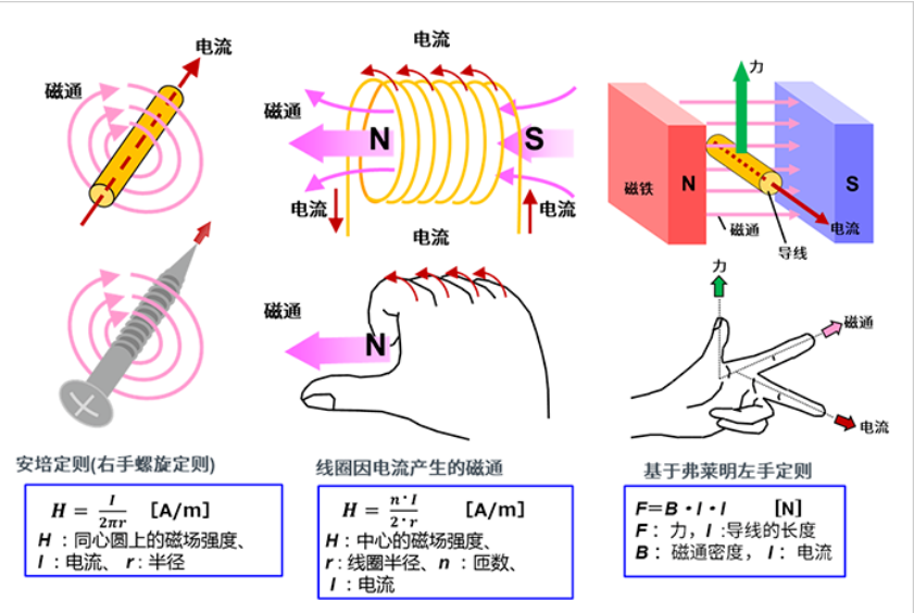
เรารวมรูปภาพและสูตรเพื่อแสดงให้เห็น

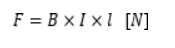
เมื่อเฟรมลวดเป็นรูปสี่เหลี่ยมผืนผ้าแรงที่กระทำในกระแสจะถูกนำมาพิจารณา
แรงที่ดำเนินการในส่วนของข้าง A และ C คือ
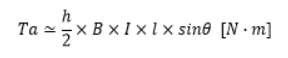
แรงบิดถูกสร้างขึ้นด้วยแกนกลางเป็นแกนกลาง
ตัวอย่างเช่นเมื่อพิจารณาสถานะที่มุมการหมุนเป็นเพียงθแรงที่ทำหน้าที่ในมุมขวาถึง B และ D คือsinθดังนั้นแรงบิดของ TA ของชิ้นส่วนจะได้รับโดย:
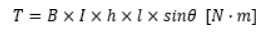
เมื่อพิจารณาส่วน C ในลักษณะเดียวกันแรงบิดจะเพิ่มขึ้นเป็นสองเท่าและสร้างแรงบิดที่คำนวณโดยสมการต่อไปนี้
เนื่องจากพื้นที่ของสี่เหลี่ยมคือ S = H ・ L การแทนที่มันลงในสมการด้านบนให้ผลลัพธ์ต่อไปนี้
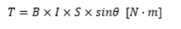
สูตรไม่เพียงใช้กับสี่เหลี่ยม แต่ยังรวมถึงรูปร่างทั่วไปอื่น ๆ เช่นวงกลม มอเตอร์ใช้ประโยชน์จากหลักการนี้
How does a electric motor rotate?
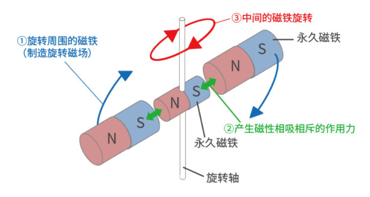
1) มอเตอร์เหนี่ยวนำหมุนด้วยความช่วยเหลือของแม่เหล็กและแรงแม่เหล็ก
รอบแม่เหล็กถาวรที่มีเพลาหมุน
①แม่เหล็กหมุน (เพื่อให้สนามแม่เหล็กหมุนถูกสร้างขึ้น)
②จากนั้นตามหลักการที่ว่าเสา n และ s ดึงดูดซึ่งกันและกันที่เสาต่าง ๆ และขับไล่ซึ่งกันและกันในระดับเดียวกัน
③แม่เหล็กที่มีเพลาหมุนจะหมุน
นี่คือหลักการพื้นฐานของการหมุนของมอเตอร์ AC
กระแสที่ไหลในตัวนำทำให้สนามแม่เหล็กหมุน (แรงแม่เหล็ก) รอบ ๆ มันและทำให้แม่เหล็กหมุนซึ่งเป็นจริงสถานะของการกระทำเช่นนี้
In addition, when the wire is wound in a coil shape, the magnetic force is synthesized, creating a large magnetic field flux (flux) that produces N and S poles.
In addition, by inserting an iron core into the coil-like wire, the magnetic lines of force become easy to pass through and stronger magnetic force can be generated.
2) Actual rotating motor
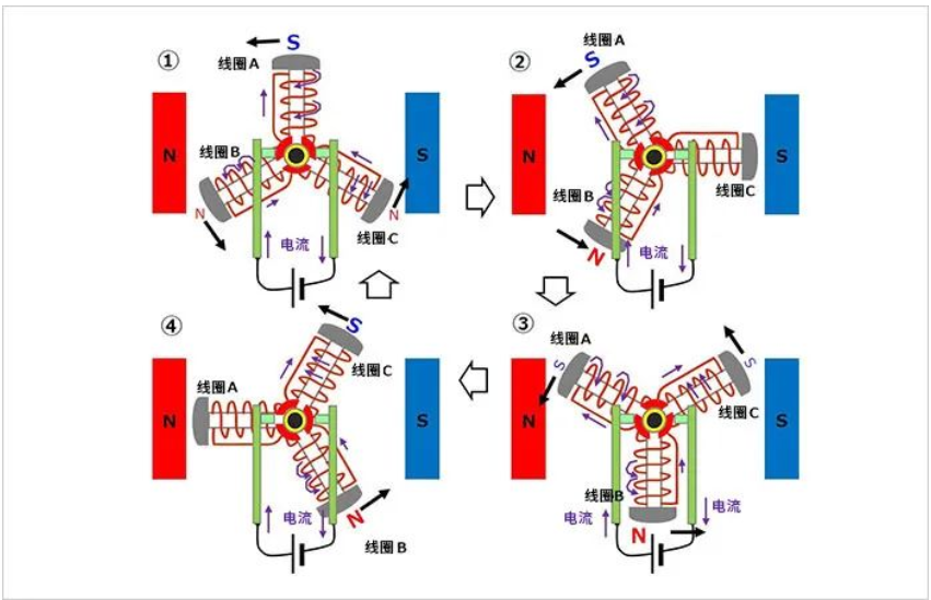
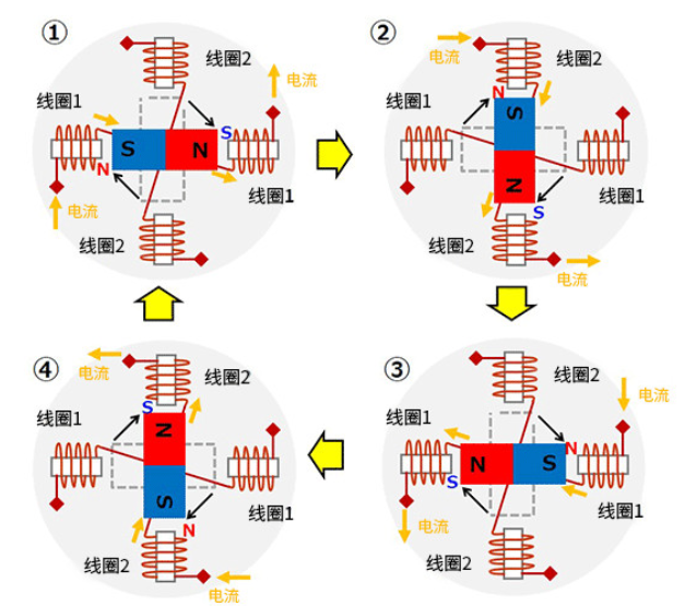
Here, as a practical method of rotating motor, we introduce the method of creating a rotating magnetic field using three-phase AC motor and coils.
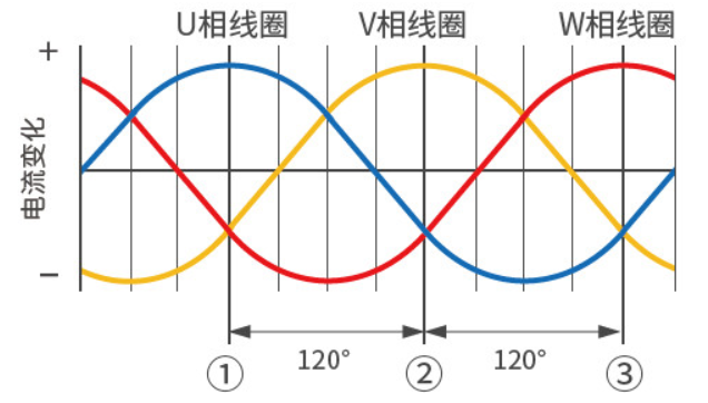
(Three-phase AC industrial motors is an AC signal spaced 120° apart in phase)
The synthetic magnetic field in the state ① above corresponds to the figure ① below.
The synthetic magnetic field in the state ② above corresponds to the figure ② below.
The synthetic magnetic field in the state ③ above corresponds to the figure ③ below.
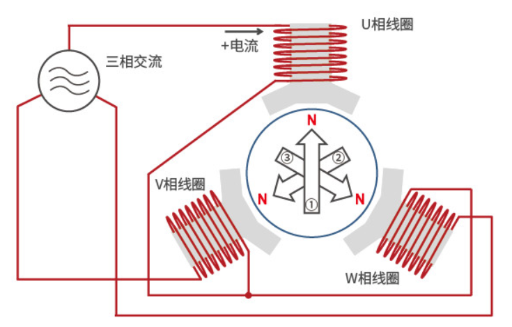
As mentioned above, the coils of the wound core are divided into three phases, with 120° interval configuration of U-phase coils, V-phase coils, and W-phase coils, with the coil with high voltage producing N-pole and the coil with low voltage producing S-pole.
Each phase changes according to a sine wave, so the polarity (N pole, S pole) and its magnetic field (magnetic force) generated by each coil will change.
At this time, the coil that produces N pole alone changes in sequence according to the U-phase coil → V-phase coil → W-phase coil → U-phase coil, and thus rotation occurs.
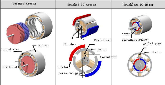
Structure of a small motor
The following figure gives the approximate structure and comparison of three types of industrial motors: stepper motors, brushed DC (DC) motors, and brushless DC (DC) motors.
The basic components of these motors are mainly coils, magnets and rotors, and there are also coil-fixed and magnet-fixed types depending on the type.
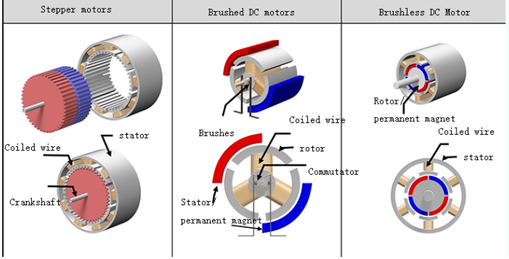
The following is a description of the structure associated with the example diagram. Since there may be other structures if divided more carefully, please understand that the structure presented in this paper is under a large frame.
The coil of the stepper motor here is fixed on the outer side and the magnet is rotated on the inner side.
Here the magnet of the brushed DC motor is fixed on the outer side and the coil rotates on the inner side. T
he brushes and commutator are responsible for supplying power to the coil and changing the direction of current.
In the case of a brushless motor, the coil is fixed on the outside and the magnet rotates on the inside.
The structure of a brushless motor is different even if the basic components are the same because of the different types of motors. The details will be explained in each section.
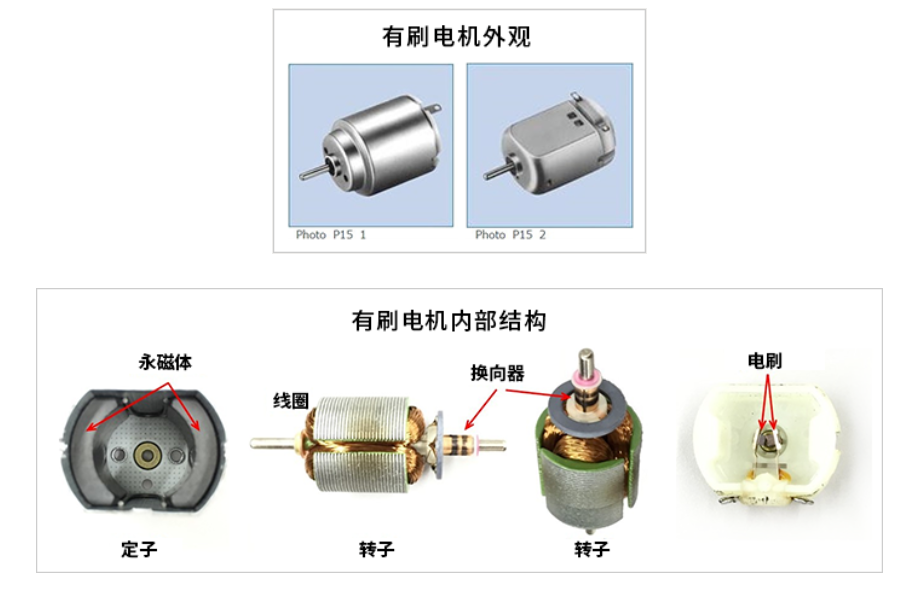
Brush motor
Structure of brushed DC motors
Below is the appearance of a brushed DC motor often used in models, and a schematic diagram of the breakdown of a normal two-pole (2 magnets) three-slot (3 coils) type motor. Perhaps many of you have experience in disassembling the dc electric motor and taking out the magnets.
You can see that the permanent magnets of a brushed DC motor are fixed, and the coils of a brushed DC motor can rotate around the internal center.
The fixed side is called the "stator" and the rotating side is called the "rotor".
The following is a structural sketch representing the concept of structure.
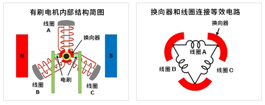
The periphery of the rotating central axis has three commutators (bent metal sheets for current switching).
เพื่อหลีกเลี่ยงการติดต่อซึ่งกันและกันผู้เดินทางจะได้รับการกำหนดค่า 120 ° (360 °÷ 3 ชิ้น) ผู้เดินทางหมุนไปด้วยการหมุนของเพลา
หนึ่ง commutator เชื่อมต่อกับปลายขดลวดหนึ่งและปลายขดลวดอื่น ๆ และสาม commutators และทั้งสามขดลวดสร้างทั้งหมด (แหวน) เป็นเครือข่ายวงจร
แปรงสองตัวได้รับการแก้ไขที่ 0 °และ 180 °เพื่อติดต่อกับตัวเลือก
แหล่งจ่ายไฟ DC ภายนอกเชื่อมต่อกับแปรงและกระแสกระแสในแปรงเส้นทาง→ Commutator → Coil → Brush
หลักการหมุนของมอเตอร์ DC แปรง
①หมุนทวนเข็มนาฬิกาจากสถานะเริ่มต้น
คอยล์ A อยู่ที่ส่วนบนสุดและเชื่อมต่อเครื่องมือไฟฟ้าที่จ่ายไปยังแปรงตั้งค่าด้านซ้ายเป็น (+) และด้านขวาเป็น (-)
กระแสไฟฟ้าขนาดใหญ่จากแปรงซ้ายผ่านเครื่องผูกไปยังขดลวด A.
นี่คือโครงสร้างที่ส่วนบน (ด้านนอก) ของขดลวด A กลายเป็นเสา S
และตั้งแต่ 1/2 ของกระแสจากขดลวด A ไหลจากแปรงซ้ายไปยังขดลวด B และ C ในทิศทางตรงกันข้ามของขดลวด A ด้านนอกของขดลวด B และ C กลายเป็น N-poles ที่อ่อนแอ (ระบุด้วยตัวอักษรที่เล็กกว่าเล็กน้อยในรูป)
สนามแม่เหล็กที่สร้างขึ้นในขดลวดเหล่านี้และเอฟเฟกต์ที่น่ารังเกียจและน่าดึงดูดของแม่เหล็กทำให้ขดลวดถูกแรงหมุนทวนเข็มนาฬิกา
②การหมุนทวนเข็มนาฬิกาเพิ่มเติม
Next, assume that the right brush is in contact with both commutators in a state where coil A is rotated 30° counterclockwise.
The current of coil A flows continuously from the left brush through the right brush and the outer side of the coil remains S-pole.
The same current as coil A flows through coil B, and the outer side of coil B becomes stronger N-pole.
Since the ends of coil C are shorted by the brushes, no current flows and no magnetic field is generated.
Even in this case, there is a counterclockwise rotating force.
The coil on the upper side from ③ to ④ is continuously subjected to a force moving to the left, and the lower coil is continuously subjected to a force moving to the right, and continues to rotate counterclockwise
When the coil rotates every 30° to ③ and ④, the outer side of the coil becomes the S pole when the coil is above the central horizontal axis; when the coil is below, it becomes the N pole, and the motion is repeated.
In other words, the upper coil is repeatedly subjected to a force moving to the left and the lower coil is repeatedly subjected to a force moving to the right (both counterclockwise). This causes the rotor to rotate counterclockwise at all times.
If power is connected to the opposite left brush (-) and right brush (+), a magnetic field is generated in the coils stator windings in the opposite direction, so the force applied to the coils moves in the opposite direction and becomes clockwise rotation.
In addition, when the power is disconnected, the rotor of the brushed motor stops spinning because it is deprived of the magnetic field that keeps it spinning.
Three-phase full-wave brushless motor
Appearance and structure of a three-phase full-wave brushless motor
The following figure shows an example of the appearance and structure of a brushless motor.
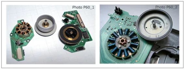
ทางด้านซ้ายเป็นตัวอย่างของมอเตอร์แกนหมุนที่ใช้ในการหมุนแผ่นดิสก์ในอุปกรณ์เล่นดิสก์ มี 9 ขดลวดสามเฟส x 3 ทางด้านขวาเป็นตัวอย่างของมอเตอร์แกนหมุนสำหรับอุปกรณ์ FDD ที่มี 12 ขดลวด (สามเฟส x 4) ขดลวดได้รับการแก้ไขบนกระดานและแผลบนแกนกลาง
ส่วนที่มีรูปดิสก์ที่ด้านขวาของขดลวดคือใบพัดแม่เหล็กถาวร เพลาโรเตอร์จะถูกแทรกเข้าไปในศูนย์กลางของขดลวดและครอบคลุมส่วนขดลวดและแม่เหล็กถาวรล้อมรอบรอบนอกของขดลวด
โครงสร้างภายในของมอเตอร์ไร้คลื่นเต็มสามเฟสและวงจรที่เทียบเท่าของการเชื่อมต่อขดลวด
ถัดไปคือร่างของโครงสร้างภายในและวงจรที่เทียบเท่าของการเชื่อมต่อขดลวด
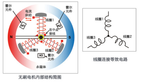
This internal structure sketch is an example of a 2-pole (2 magnets) 3-slot (3 coils) motor with a very simple structure. It is similar to the structure of a brushed motor with the same number of poles and slots, but the coil side is fixed and the magnets can be rotated. Of course, there are no brushes.
In this case, the coils are connected in a Y-shape and a semiconductor element is used to supply current to the coils, controlling the inflow and outflow of current according to the position of the rotating magnets.
In this example, a Hall element is used to detect the position of the magnet. The Hall element is configured between the coil and the coil to detect the voltage generated and used as position information based on the magnetic field strength. In the image of the FDD spindle motor given earlier, you can also see the Hall element used to detect the position between the coil and the coil (above the coil).
Hall elements are well known as magnetic sensors.
It can convert the magnitude of the magnetic field into the magnitude of the voltage and indicate the direction of the magnetic field in positive or negative terms.
Below is a diagram showing the Hall effect.
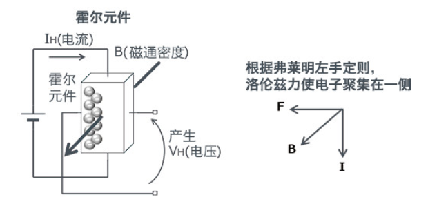
Hall elements take advantage of the phenomenon that "when a current IH flows through a semiconductor and the magnetic flux B passes at right angles to the current, a voltage VH is generated in the direction perpendicular to the current and the magnetic field", a phenomenon discovered by American physicist Edwin Herbert Hall (Edwin Herbert Hall) and called "Hall effect".
The resulting voltage VH is expressed by the following equation.
VH = (KH / d)・IH・B ※KH: Hall coefficient, d: thickness of flux penetration surface
As the formula shows, the higher the current, the higher the voltage. This property is often used to detect the position of the rotor (magnet).
Rotation principle of three-phase full-wave brushless motor
The rotation principle of the brushless motor will be explained in the following steps ① to ⑥. For easy understanding, the permanent magnet is simplified from a circle to a rectangle here.
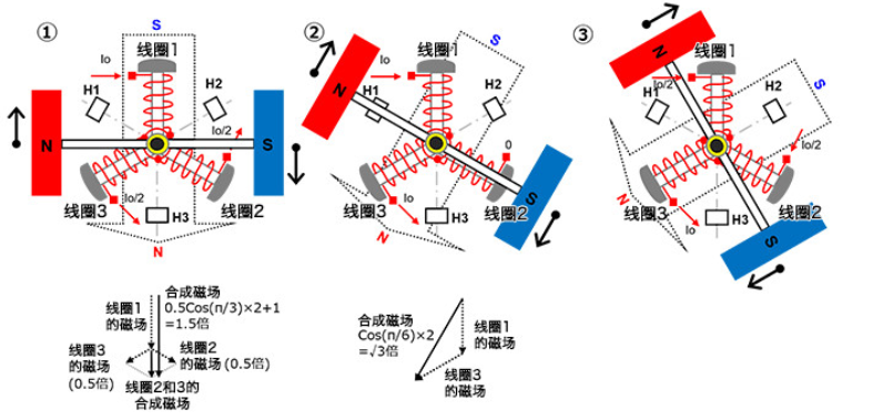
①
In a 3-phase coil, let coil 1 be fixed at 12 o'clock, coil 2 be fixed at 4 o'clock and coil 3 be fixed at 8 o'clock of the clock. Let the N-pole of the 2-pole permanent magnet be on the left side and the S-pole on the right side and rotatable.
Make the current Io flow into coil 1 to produce the S-pole magnetic field on the outside of the coil. Let the current Io/2 flow out of coil 2 and coil 3 to produce an N-pole magnetic field on the outside of the coil.
When the magnetic fields of coils 2 and 3 are vector synthesized, the N-pole magnetic field is generated downward, which is 0.5 times the size of the magnetic field generated when the current Io passes through a coil, and becomes 1.5 times the size when added to the magnetic field of coil 1. This produces a synthetic magnetic field at an angle of 90° with respect to the permanent magnet, so that the maximum torque can be generated and the permanent magnet rotates clockwise.
When the current in coil 2 is reduced and the current in coil 3 is increased according to the rotating position, the synthetic magnetic field also rotates clockwise and the permanent magnet continues to rotate.
②
ในสถานะหมุนของ 30 °กระแส IO ไหลเข้าสู่ขดลวด 1 เพื่อให้กระแสในคอยล์ 2 เป็นศูนย์ทำให้กระแส IO ไหลออกจากขดลวด 3
ด้านนอกของขดลวด 1 กลายเป็นเสา S และด้านนอกของขดลวด 3 กลายเป็นขั้ว N เมื่อเวกเตอร์ถูกสังเคราะห์สนามแม่เหล็กที่เกิดขึ้นคือ√3 (≈1.72) เท่าสนามแม่เหล็กที่เกิดขึ้นเมื่อกระแส IO ผ่านขดลวดเดียว นอกจากนี้ยังสร้างสนามแม่เหล็กสังเคราะห์ที่มุม 90 °เมื่อเทียบกับสนามแม่เหล็กของแม่เหล็กถาวรและหมุนตามเข็มนาฬิกา
เมื่อกระแสการไหลเข้าของ IO ของขดลวด 1 ลดลงตามตำแหน่งการหมุนกระแสการไหลเข้าของขดลวด 2 จะเพิ่มขึ้นจากศูนย์และกระแสไหลออกของขดลวด 3 จะเพิ่มขึ้นเป็น IO สนามแม่เหล็กสังเคราะห์ก็หมุนตามเข็มนาฬิกาและแม่เหล็กถาวรยังคงหมุน
Assuming that the current in each phase is sinusoidal, the current value here is Io × sin(π⁄3) = Io × √3⁄2. By vector synthesis of the magnetic field, the total magnetic field size is (√3⁄2)2 × 2 = 1.5 times the magnetic field generated by one coil. When the currents in each phase are sinusoidal, the magnitude of the vector synthesis magnetic field is 1.5 times the magnetic field produced by one coil regardless of the position of the permanent magnet, and the magnetic field is at an angle of 90° with respect to the magnetic field of the permanent magnet.
③
ในสถานะที่การหมุนยังคงดำเนินต่อไปเป็นเวลา 30 °กระแส IO/2 กระแสไหลเข้าสู่ขดลวด 1 กระแส IO/2 กระแสไหลเข้าสู่ขดลวด 2 และกระแส IO ไหลออกมาจากขดลวด 3
ด้านนอกของขดลวด 1 กลายเป็นเสา S ด้านนอกของขดลวด 2 ก็กลายเป็นขั้ว S และด้านนอกของขดลวด 3 กลายเป็นขั้ว N เมื่อเวกเตอร์ถูกสังเคราะห์สนามแม่เหล็กที่เกิดขึ้นคือ 1.5 เท่าของสนามแม่เหล็กที่เกิดขึ้นเมื่อ IO กระแสไหลผ่านขดลวดเดียว (เหมือนกับ①) ที่นี่เช่นกันสนามแม่เหล็กสังเคราะห์ถูกสร้างขึ้นที่มุม 90 °เมื่อเทียบกับสนามแม่เหล็กของแม่เหล็กถาวรและหมุนตามเข็มนาฬิกา
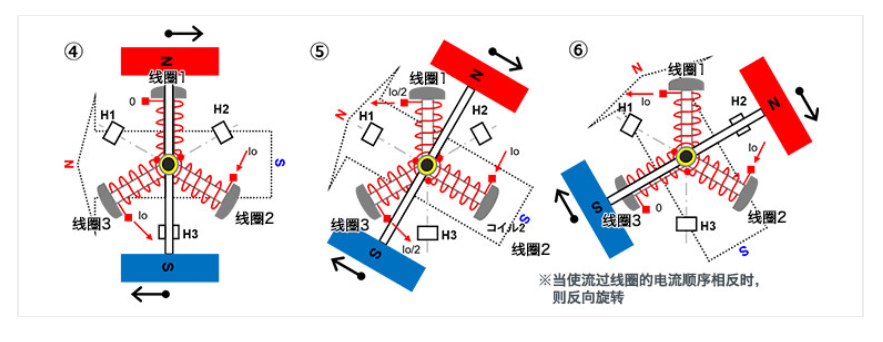
④~⑥
หมุนในลักษณะเดียวกับ①ถึง③
In this way, if the current flowing into the coil is continuously switched sequentially according to the position of the permanent magnet, the permanent magnet will rotate in a fixed direction. Similarly, if the current is reversed and the direction of the synthetic magnetic field is reversed, it will rotate counterclockwise.
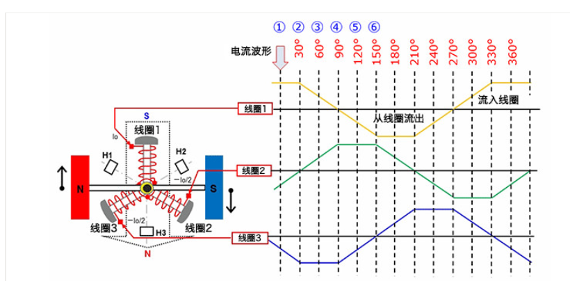
The following diagram shows the currents in each coil for each of the steps ① to ⑥ above in succession. The relationship between current change and rotation should be understood by the above description.
สเต็ปเปอร์มอเตอร์
A stepper motor is a motor that can accurately control the rotation angle and speed synchronized with a pulse signal, also known as a "pulse motor. Stepper motors are widely used in equipment that requires positioning because accurate positioning can be achieved by open-loop control without the use of position sensors.
Structure of stepper motor (two-phase bipolar)
The following diagrams, from left to right, show an example of the appearance of a stepper motor, a sketch of the internal structure, and a sketch of the structure concept.
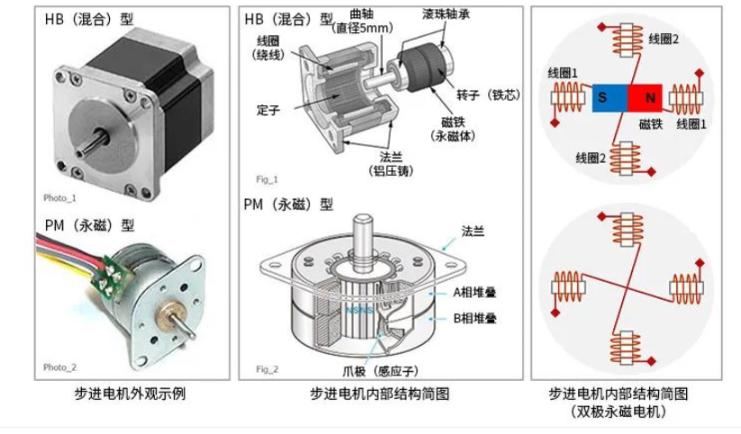
In the appearance example, the appearance of HB (hybrid) type and PM (permanent magnet) type stepper motors are given. The structure diagram in the middle is also given for the HB type and PM type.
มอเตอร์สเต็ปเปอร์เป็นโครงสร้างที่ขดลวดคงที่และแม่เหล็กถาวรหมุน แผนภาพแนวคิดของโครงสร้างภายในของมอเตอร์สเต็ปทางด้านขวาเป็นตัวอย่างของมอเตอร์ PM โดยใช้ขดลวดสองเฟส (สองชุด) ในตัวอย่างโครงสร้างมอเตอร์สเต็ปส์ขั้นพื้นฐานนั้นจะถูกกำหนดค่าไว้ที่ด้านนอกและแม่เหล็กถาวรจะถูกกำหนดค่าไว้ด้านใน นอกเหนือจากขดลวดสองเฟสแล้วยังมีประเภทที่มีจำนวนเฟสจำนวนมากขึ้นเช่นสามเฟสและห้าเฟส
Some stepper motors have other different structures, but the basic structure of the stepper motor is given in this paper to facilitate the introduction of its operating principle. Through this paper, we hope to understand the basic structure of stepper motors with fixed coils and rotating permanent magnets.
Basic working principle of stepper motor (single-phase excitation)
แผนภาพต่อไปนี้ใช้เพื่อแนะนำหลักการทำงานพื้นฐานของมอเตอร์สเต็ปเปอร์ นี่คือตัวอย่างของการกระตุ้นสำหรับแต่ละเฟส (ชุดขดลวด) ของขดลวดสองขั้วสองเฟสด้านบน หลักฐานของแผนภาพคือรัฐเปลี่ยนจาก①เป็น④ ขดลวดประกอบด้วยขดลวด 1 และขดลวด 2 ตามลำดับ นอกจากนี้ลูกศรปัจจุบันระบุทิศทางของการไหลของกระแสไฟฟ้า
①
・ สร้างกระแสกระแสจากด้านซ้ายของขดลวด 1 และออกจากด้านขวาของขดลวด 1
・ ไม่อนุญาตให้กระแสไหลผ่านขดลวด 2
・ ในเวลานี้ด้านในของขดลวดซ้าย 1 กลายเป็น n และด้านในของขดลวดขวา 1 กลายเป็น S.
・As a result, the middle permanent magnet is attracted by the magnetic field of coil 1 and changes to the left side S and the right side N and stops.
②
・The current of coil 1 is stopped so that the current flows in from the upper side of coil 2 and out from the lower side of coil 2.
・The inner side of upper coil 2 changes to N and the inner side of lower coil 2 changes to S.
・The permanent magnet is attracted by its magnetic field and rotates 90° clockwise to stop.
③
・The current of coil 2 is stopped so that the current flows in from the right side of coil 1 and out from the left side of coil 1.
・The inner side of the left coil 1 becomes S and the inner side of the right coil 1 becomes N.
・The permanent magnet is attracted by its magnetic field and rotates clockwise by another 90° to stop.
④
・Stop the current in coil 1 so that the current flows in from the lower side of coil 2 and out from the upper side of coil 2.
・The inner side of upper coil 2 becomes S and the inner side of lower coil 2 becomes N.
・The permanent magnet is attracted by its magnetic field and rotates clockwise by another 90° to stop.
The stepper motor can be rotated by switching the current flowing through the coil by the electronic circuit in the order of ① to ④ above. In this example, each switching action causes the stepper motor to rotate 90°.
In addition, when the current is continuously flowing through a coil, the stop state can be maintained and the stepper motor can have a holding torque. Incidentally, if the order of the current flowing through the coil is reversed, the stepper motor can be made to rotate in reverse.
Find a professional industrial motor manufacturer - Dongchun motor China