Skip naar inhoud
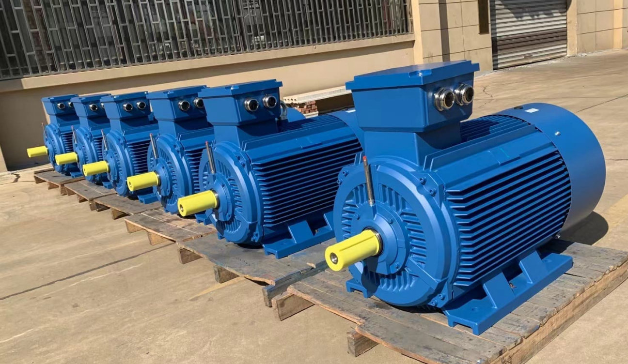
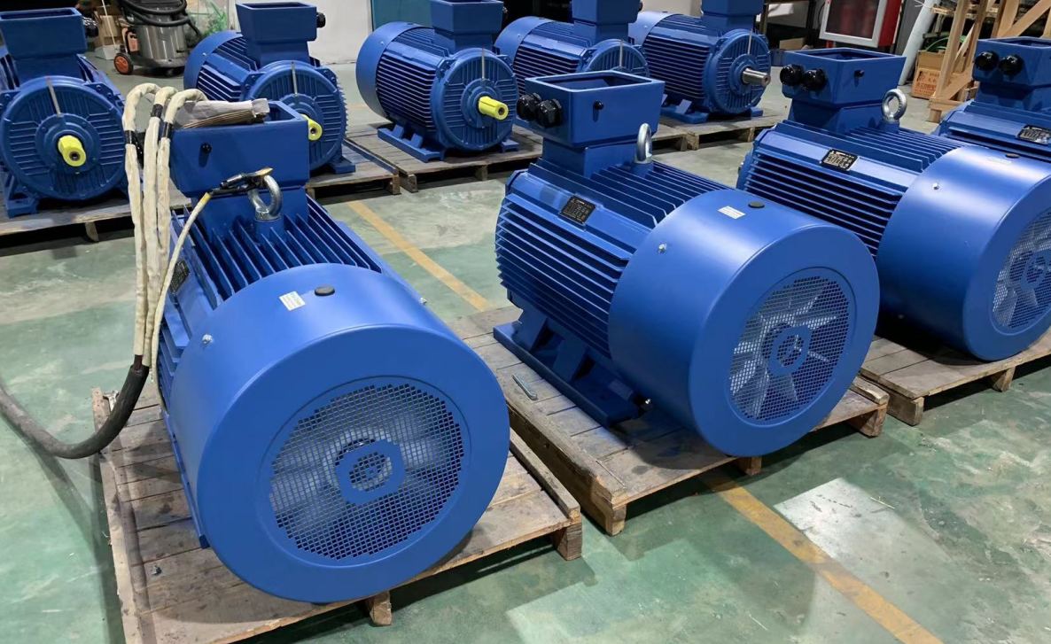
Bijna de helft van het energieverbruik in de wereld wordt verbruikt door elektromotoren, dus het hoge rendement van elektromotoren zou de meest effectieve maatregel zijn bij het oplossen van de energieproblemen in de wereld.
Soorten elektromotoren
In het algemeen verwijst het naar de transformatie van de kracht die wordt gegenereerd door de stroom van stroom in een magnetisch veld in een roterende actie, en in een breed bereik omvat het ook lineaire actie.
Afhankelijk van het type voeding dat wordt gebruikt om de motor aan te drijven, zijn er gelijkstroommotoren en AC-elektromotoren.
En volgens het motorrotatieprincipe kan het grofweg in de volgende categorieën worden verdeeld. (Behalve speciale motoren)
DC-elektromotor/DC-motoren (gelijkstroom).
Geborstelde motoren
De veelgebruikte borstelmotoren worden over het algemeen DC-elektromotoren genoemd.
The electrodes connected to the "brush" (stator side) and the "commutator" (armature side)
The brushed motor is used to switch the current by making contact with the "commutator" (armature side) in turn to perform rotational action.
Borstelloze gelijkstroommotor
Borstelloze gelijkstroommotoren gebruiken geen borstels of commutatoren, maar gebruiken een schakelfunctie zoals een transistor om de stroom te schakelen en een roterende actie uit te voeren.
Stappenmotor.
Deze motor werkt synchroon met pulsvermogen en wordt daarom ook wel pulsinductiemotor genoemd.
Het wordt gekenmerkt door het vermogen om eenvoudig een nauwkeurige positionering te bereiken.
AC -motoren
Asynchrone motor
AC power generates a rotating magnetic field in the stator, which in turn generates an induced current in the rotor, in whose interaction rotation occurs for the ac induction motor.
Synchronous motor
AC power creates a rotating magnetic field, and the rotor with magnetic poles rotates due to the attraction.
-The speed of rotation is fortunately synchronized with the frequency of the power supply.
Over stromingen, magnetische velden en krachten
First, for the sake of subsequent motor principle explanations, let's review the basic laws/laws regarding current, magnetic field and force.
Although there is a feeling of nostalgia, it is easy to forget this knowledge if you do not usually use magnetic components
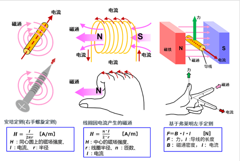
We combine pictures and formulas to illustrate.

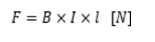
Wanneer het draadframe rechthoekig is, wordt rekening gehouden met de kracht die op de stroom inwerkt.
De kracht F die op de delen van zijden a en c inwerkt, is
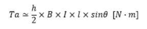
Het koppel wordt gegenereerd met de centrale as als centrale as.
Als we bijvoorbeeld een toestand beschouwen waarin de rotatiehoek slechts θ is, is de kracht die loodrecht op b en d werkt sinθ, dus het koppel Ta van het a-onderdeel wordt gegeven door:
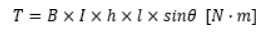
Als we op dezelfde manier deel c beschouwen, wordt het koppel verdubbeld en ontstaat het koppel dat wordt berekend met de volgende vergelijking
Omdat de oppervlakte van de rechthoek S = h・l is, geeft het vervangen ervan in de bovenstaande vergelijking het volgende resultaat.
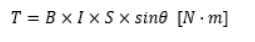
The formula applies not only to rectangles, but also to other common shapes such as circles. The motor makes use of this principle.
Hoe draait een elektromotor?
1) The induction motors rotate with the help of magnets and magnetic force
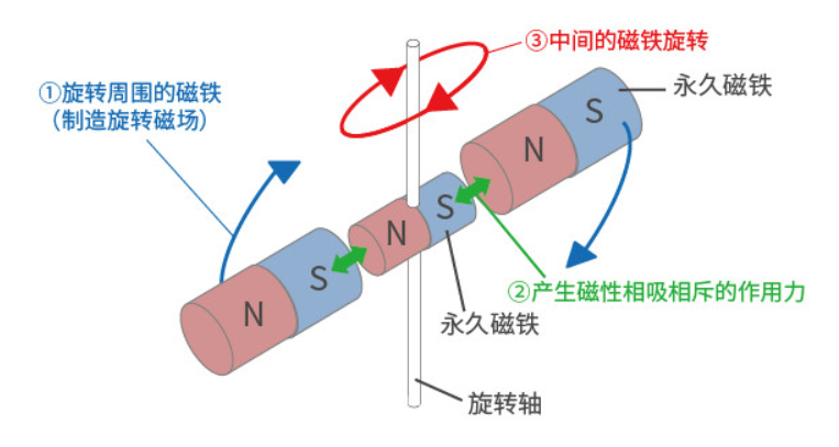
Around a permanent magnet with a rotating shaft,
① the magnet is rotated (so that a rotating magnetic field is generated),
② then according to the principle that N and S poles attract each other at different poles and repel each other at the same level,
③ the magnet with a rotating shaft will rotate.
This is the basic principle of ac motors rotation.
The current flowing in the conductor causes a rotating magnetic field (magnetic force) around it and thus the magnet rotates, which is practically the same state of action as this.
In addition, when the wire is wound in a coil shape, the magnetic force is synthesized, creating a large magnetic field flux (flux) that produces N and S poles.
In addition, by inserting an iron core into the coil-like wire, the magnetic lines of force become easy to pass through and stronger magnetic force can be generated.
2) Actual rotating motor
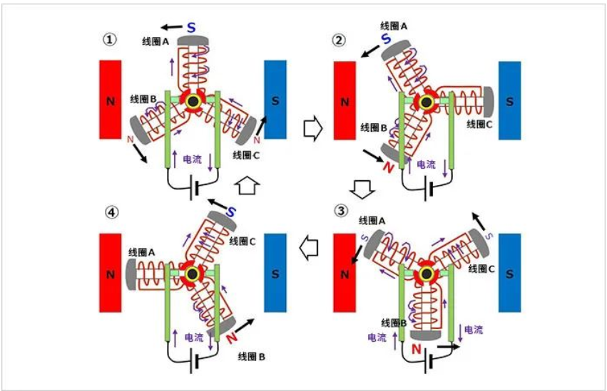
Here, as a practical method of rotating motor, we introduce the method of creating a rotating magnetic field using three-phase AC motor and coils.
(Three-phase AC industrial motors is an AC signal spaced 120° apart in phase)
The synthetic magnetic field in the state ① above corresponds to the figure ① below.
The synthetic magnetic field in the state ② above corresponds to the figure ② below.
The synthetic magnetic field in the state ③ above corresponds to the figure ③ below.
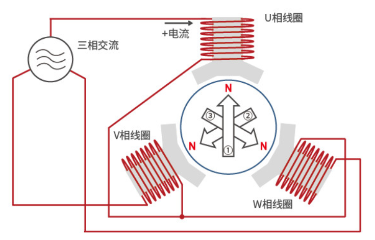
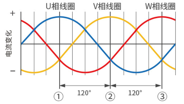
As mentioned above, the coils of the wound core are divided into three phases, with 120° interval configuration of U-phase coils, V-phase coils, and W-phase coils, with the coil with high voltage producing N-pole and the coil with low voltage producing S-pole.
Each phase changes according to a sine wave, so the polarity (N pole, S pole) and its magnetic field (magnetic force) generated by each coil will change.
At this time, the coil that produces N pole alone changes in sequence according to the U-phase coil → V-phase coil → W-phase coil → U-phase coil, and thus rotation occurs.
Structuur van een kleine motor
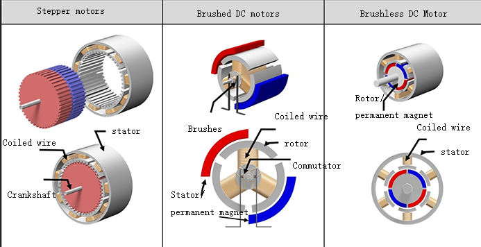
The following figure gives the approximate structure and comparison of three types of industrial motors: stepper motors, brushed DC (DC) motors, and brushless DC (DC) motors.
The basic components of these motors are mainly coils, magnets and rotors, and there are also coil-fixed and magnet-fixed types depending on the type.
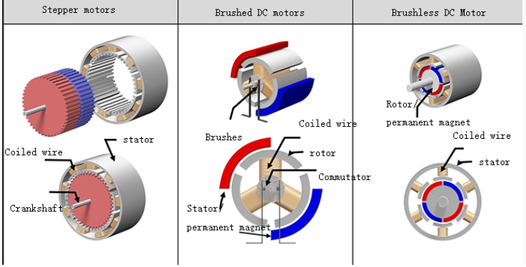
The following is a description of the structure associated with the example diagram. Since there may be other structures if divided more carefully, please understand that the structure presented in this paper is under a large frame.
The coil of the stepper motor here is fixed on the outer side and the magnet is rotated on the inner side.
Here the magnet of the brushed DC motor is fixed on the outer side and the coil rotates on the inner side. T
he brushes and commutator are responsible for supplying power to the coil and changing the direction of current.
In the case of a brushless motor, the coil is fixed on the outside and the magnet rotates on the inside.
The structure of a brushless motor is different even if the basic components are the same because of the different types of motors. The details will be explained in each section.
Borstelmotor
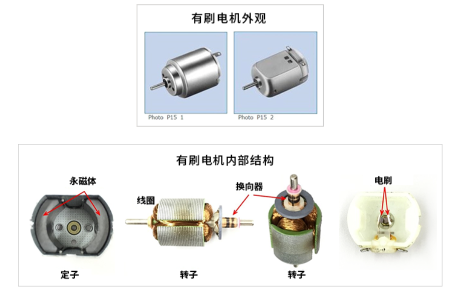
Structure of brushed DC motors
Below is the appearance of a brushed DC motor often used in models, and a schematic diagram of the breakdown of a normal two-pole (2 magnets) three-slot (3 coils) type motor. Perhaps many of you have experience in disassembling the dc electric motor and taking out the magnets.
You can see that the permanent magnets of a brushed DC motor are fixed, and the coils of a brushed DC motor can rotate around the internal center.
The fixed side is called the "stator" and the rotating side is called the "rotor".
The following is a structural sketch representing the concept of structure.
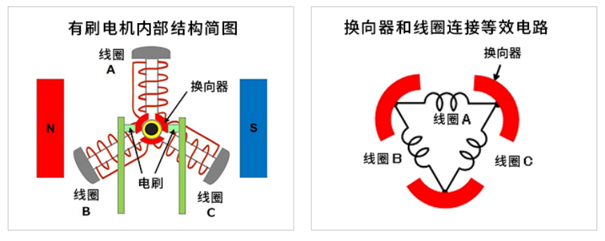
The periphery of the rotating central axis has three commutators (bent metal sheets for current switching).
To avoid contact with each other, the commutators are configured 120° apart (360° ÷ 3 pieces). The commutators rotate with the rotation of the shaft.
One commutator is connected to one coil end and the other coil end, and the three commutators and the three coils form a whole (ring) as a circuit network.
Two brushes are fixed at 0° and 180° to make contact with the commutator.
An external DC power supply is connected to the brushes and the current flows in the path brush → commutator → coil → brush.
Rotation principle of brush dc motor
① Rotate counterclockwise from the initial state
Coil A is at the uppermost part and connects the power tools supply to the brushes, set the left side as (+) and the right side as (-).
A large current flows from the left brush through the commutator to coil A.
This is the structure where the upper part (outside) of coil A becomes the S pole.
And since 1/2 of the current from coil A flows from the left brush to coils B and C in the opposite direction of coil A, the outer sides of coils B and C become weak N-poles (indicated by slightly smaller letters in the figure).
The magnetic fields generated in these coils and the repulsive and attractive effects of the magnets cause the coils to be subjected to a counterclockwise rotating force.
② Further counterclockwise rotation
Next, assume that the right brush is in contact with both commutators in a state where coil A is rotated 30° counterclockwise.
The current of coil A flows continuously from the left brush through the right brush and the outer side of the coil remains S-pole.
The same current as coil A flows through coil B, and the outer side of coil B becomes stronger N-pole.
Since the ends of coil C are shorted by the brushes, no current flows and no magnetic field is generated.
Even in this case, there is a counterclockwise rotating force.
The coil on the upper side from ③ to ④ is continuously subjected to a force moving to the left, and the lower coil is continuously subjected to a force moving to the right, and continues to rotate counterclockwise
When the coil rotates every 30° to ③ and ④, the outer side of the coil becomes the S pole when the coil is above the central horizontal axis; when the coil is below, it becomes the N pole, and the motion is repeated.
In other words, the upper coil is repeatedly subjected to a force moving to the left and the lower coil is repeatedly subjected to a force moving to the right (both counterclockwise). This causes the rotor to rotate counterclockwise at all times.
If power is connected to the opposite left brush (-) and right brush (+), a magnetic field is generated in the coils stator windings in the opposite direction, so the force applied to the coils moves in the opposite direction and becomes clockwise rotation.
In addition, when the power is disconnected, the rotor of the brushed motor stops spinning because it is deprived of the magnetic field that keeps it spinning.
Borstelloze driefasige dubbelgolfmotor
Appearance and structure of a three-phase full-wave brushless motor
The following figure shows an example of the appearance and structure of a brushless motor.
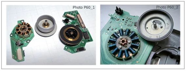
On the left is an example of a spindle motor used to rotate a disc in a disc playback device. There are 9 coils of three phases x 3. On the right is an example of a spindle motor for an FDD device with 12 coils (three-phase x 4). The coils are fixed on the board and wound on the core.
The disk-shaped part on the right side of the coils is the permanent magnet rotor. The rotor shaft is inserted into the center of the coil and covers the coil part, and the permanent magnets surround the periphery of the coil.
The internal structure of the three-phase full-wave brushless motor and the equivalent circuit of the coil connection
Next is a sketch of the internal structure and the equivalent circuit of the coil connection.
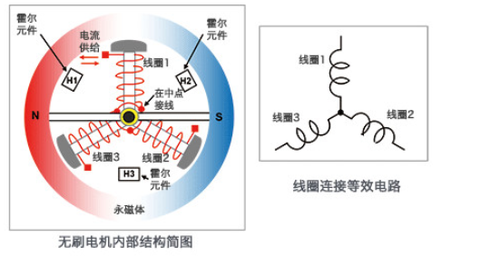
This internal structure sketch is an example of a 2-pole (2 magnets) 3-slot (3 coils) motor with a very simple structure. It is similar to the structure of a brushed motor with the same number of poles and slots, but the coil side is fixed and the magnets can be rotated. Of course, there are no brushes.
In this case, the coils are connected in a Y-shape and a semiconductor element is used to supply current to the coils, controlling the inflow and outflow of current according to the position of the rotating magnets.
In dit voorbeeld wordt een Hall-element gebruikt om de positie van de magneet te detecteren. Het Hall-element is geconfigureerd tussen de spoel en de spoel om de gegenereerde spanning te detecteren en te gebruiken als positie-informatie op basis van de magnetische veldsterkte. In de eerder gegeven afbeelding van de FDD-spilmotor ziet u ook het Hall-element dat wordt gebruikt om de positie tussen de spoel en de spoel (boven de spoel) te detecteren.
Hall-elementen staan bekend als magnetische sensoren.
Het kan de grootte van het magnetische veld omzetten in de grootte van de spanning en de richting van het magnetische veld in positieve of negatieve termen aangeven.
Hieronder ziet u een diagram dat het Hall-effect laat zien.
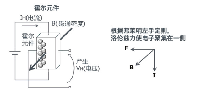
Hall elements take advantage of the phenomenon that "when a current IH flows through a semiconductor and the magnetic flux B passes at right angles to the current, a voltage VH is generated in the direction perpendicular to the current and the magnetic field", a phenomenon discovered by American physicist Edwin Herbert Hall (Edwin Herbert Hall) and called "Hall effect".
The resulting voltage VH is expressed by the following equation.
VH = (KH / d)・IH・B ※KH: Hall coefficient, d: thickness of flux penetration surface
As the formula shows, the higher the current, the higher the voltage. This property is often used to detect the position of the rotor (magnet).
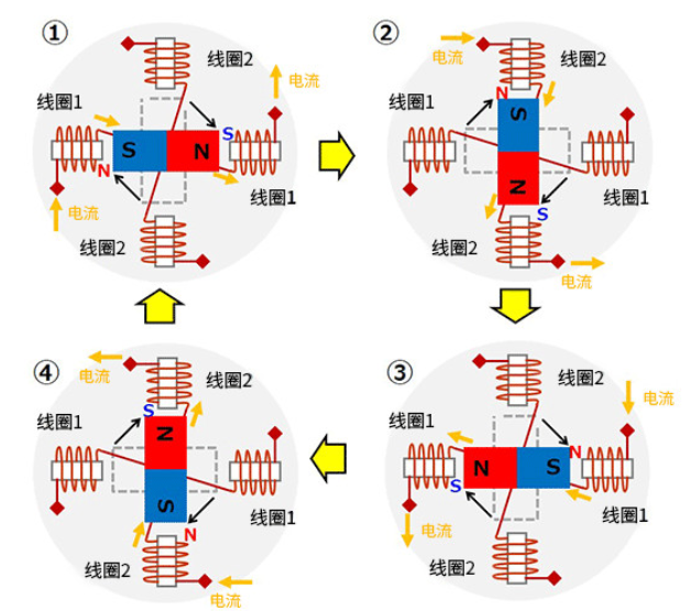
Rotation principle of three-phase full-wave brushless motor
The rotation principle of the brushless motor will be explained in the following steps ① to ⑥. For easy understanding, the permanent magnet is simplified from a circle to a rectangle here.
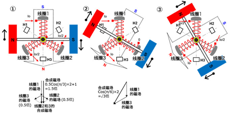
①
In a 3-phase coil, let coil 1 be fixed at 12 o'clock, coil 2 be fixed at 4 o'clock and coil 3 be fixed at 8 o'clock of the clock. Let the N-pole of the 2-pole permanent magnet be on the left side and the S-pole on the right side and rotatable.
Make the current Io flow into coil 1 to produce the S-pole magnetic field on the outside of the coil. Let the current Io/2 flow out of coil 2 and coil 3 to produce an N-pole magnetic field on the outside of the coil.
When the magnetic fields of coils 2 and 3 are vector synthesized, the N-pole magnetic field is generated downward, which is 0.5 times the size of the magnetic field generated when the current Io passes through a coil, and becomes 1.5 times the size when added to the magnetic field of coil 1. This produces a synthetic magnetic field at an angle of 90° with respect to the permanent magnet, so that the maximum torque can be generated and the permanent magnet rotates clockwise.
When the current in coil 2 is reduced and the current in coil 3 is increased according to the rotating position, the synthetic magnetic field also rotates clockwise and the permanent magnet continues to rotate.
②
In the rotated state of 30°, the current Io flows into coil 1 so that the current in coil 2 is zero, causing the current Io to flow out of coil 3.
The outer side of coil 1 becomes the S pole and the outer side of coil 3 becomes the N pole. When the vector is synthesized, the magnetic field produced is √3 (≈1.72) times the magnetic field produced when the current Io passes through one coil. This also produces a synthesized magnetic field at an angle of 90° with respect to the magnetic field of the permanent magnet, and rotates clockwise.
Wanneer de instroomstroom Io van spoel 1 wordt verminderd volgens de roterende positie, wordt de instroomstroom van spoel 2 verhoogd van nul en wordt de uitstroomstroom van spoel 3 verhoogd naar Io, roteert het synthetische magnetische veld ook met de klok mee en blijft de permanente magneet draaien.
Assuming that the current in each phase is sinusoidal, the current value here is Io × sin(π⁄3) = Io × √3⁄2. By vector synthesis of the magnetic field, the total magnetic field size is (√3⁄2)2 × 2 = 1.5 times the magnetic field generated by one coil. When the currents in each phase are sinusoidal, the magnitude of the vector synthesis magnetic field is 1.5 times the magnetic field produced by one coil regardless of the position of the permanent magnet, and the magnetic field is at an angle of 90° with respect to the magnetic field of the permanent magnet.
③
In the state where the rotation has continued for 30°, the current Io/2 flows into coil 1, the current Io/2 flows into coil 2, and the current Io flows out of coil 3.
The outer side of coil 1 becomes the S pole, the outer side of coil 2 also becomes the S pole, and the outer side of coil 3 becomes the N pole. When the vector is synthesized, the magnetic field produced is 1.5 times the magnetic field produced when the current Io flows through one coil (same as ①). Here too, a synthetic magnetic field is generated at an angle of 90° with respect to the magnetic field of the permanent magnet, and rotates clockwise.
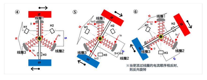
④~⑥
Rotate in the same way as ① to ③.
In this way, if the current flowing into the coil is continuously switched sequentially according to the position of the permanent magnet, the permanent magnet will rotate in a fixed direction. Similarly, if the current is reversed and the direction of the synthetic magnetic field is reversed, it will rotate counterclockwise.
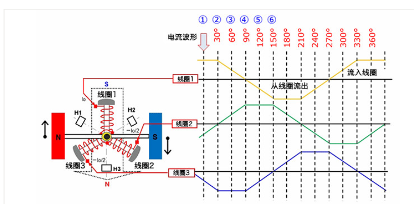
The following diagram shows the currents in each coil for each of the steps ① to ⑥ above in succession. The relationship between current change and rotation should be understood by the above description.
Stappenmotoren
A stepper motor is a motor that can accurately control the rotation angle and speed synchronized with a pulse signal, also known as a "pulse motor. Stepper motors are widely used in equipment that requires positioning because accurate positioning can be achieved by open-loop control without the use of position sensors.
Structure of stepper motor (two-phase bipolar)
The following diagrams, from left to right, show an example of the appearance of a stepper motor, a sketch of the internal structure, and a sketch of the structure concept.
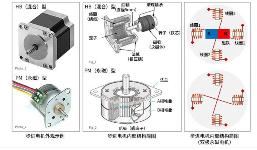
In the appearance example, the appearance of HB (hybrid) type and PM (permanent magnet) type stepper motors are given. The structure diagram in the middle is also given for the HB type and PM type.
The stepper motor is a structure in which the coil is fixed and the permanent magnet is rotating. The conceptual diagram of the internal structure of a stepper motor on the right is an example of a PM motor using two-phase (two sets) of coils. In the basic stepper motor structure example, the coils are configured on the outside and the permanent magnets are configured on the inside. In addition to two-phase coils, there are also types with a larger number of phases such as three-phase and five-phase.
Some stepper motors have other different structures, but the basic structure of the stepper motor is given in this paper to facilitate the introduction of its operating principle. Through this paper, we hope to understand the basic structure of stepper motors with fixed coils and rotating permanent magnets.
Basic working principle of stepper motor (single-phase excitation)
The following diagram is used to introduce the basic operating principle of a stepper motor. This is an example of excitation for each phase (set of coils) of the two-phase bipolar type coils above. The premise of the diagram is that the state changes from ① to ④. The coils consist of coil 1 and coil 2, respectively. In addition, the current arrows indicate the direction of current flow.
①
・Make the current flow from the left side of coil 1 and out from the right side of coil 1.
・Do not allow current to flow through coil 2.
・At this time, the inner side of the left coil 1 becomes N and the inner side of the right coil 1 becomes S.
・As a result, the middle permanent magnet is attracted by the magnetic field of coil 1 and changes to the left side S and the right side N and stops.
②
・The current of coil 1 is stopped so that the current flows in from the upper side of coil 2 and out from the lower side of coil 2.
・The inner side of upper coil 2 changes to N and the inner side of lower coil 2 changes to S.
・The permanent magnet is attracted by its magnetic field and rotates 90° clockwise to stop.
③
・The current of coil 2 is stopped so that the current flows in from the right side of coil 1 and out from the left side of coil 1.
・The inner side of the left coil 1 becomes S and the inner side of the right coil 1 becomes N.
・The permanent magnet is attracted by its magnetic field and rotates clockwise by another 90° to stop.
④
・Stop the current in coil 1 so that the current flows in from the lower side of coil 2 and out from the upper side of coil 2.
・The inner side of upper coil 2 becomes S and the inner side of lower coil 2 becomes N.
・The permanent magnet is attracted by its magnetic field and rotates clockwise by another 90° to stop.
The stepper motor can be rotated by switching the current flowing through the coil by the electronic circuit in the order of ① to ④ above. In this example, each switching action causes the stepper motor to rotate 90°.
In addition, when the current is continuously flowing through a coil, the stop state can be maintained and the stepper motor can have a holding torque. Incidentally, if the order of the current flowing through the coil is reversed, the stepper motor can be made to rotate in reverse.
Find a professional industrial motor manufacturer - Dongchun motor China