 Slaan na inhoud
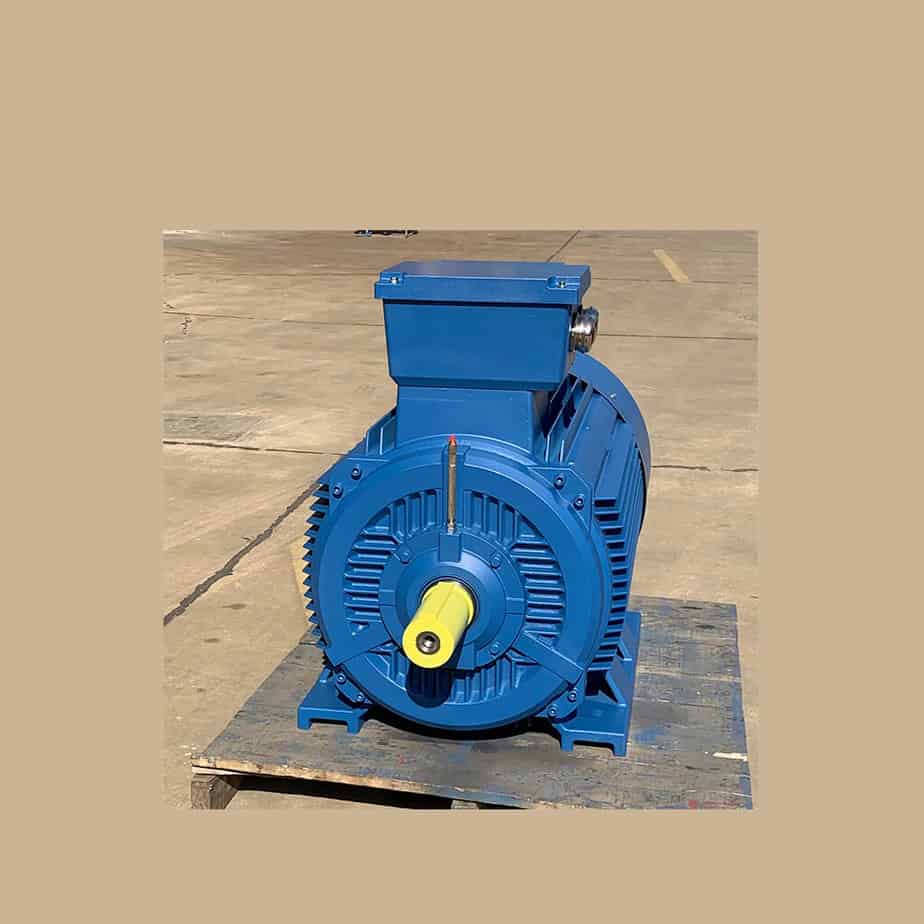
A star-delta buck start requires three contactors, a main circuit contactor, a star start contactor and a triangle run contactor.
It is best to use a time relay to control the time delay, and the main circuit contactor should be heated with an overload relay to protect the motor.
The star-delta step-down starter is only suitable for electric motors that are normally run in a triangular configuration.
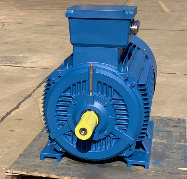
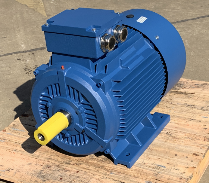
First we look at the internal windings of the induction motor.
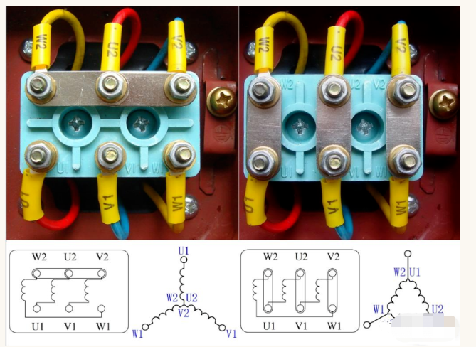
There are three internal motor windings in a three-phase asynchronous motor, with both star and triangular connections.
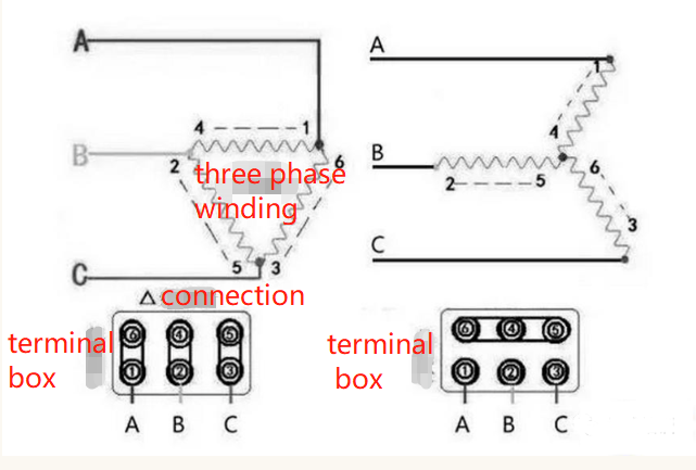
A star is where the three windings are joined together at the end, a triangle is where the three windings are joined at the beginning and end.
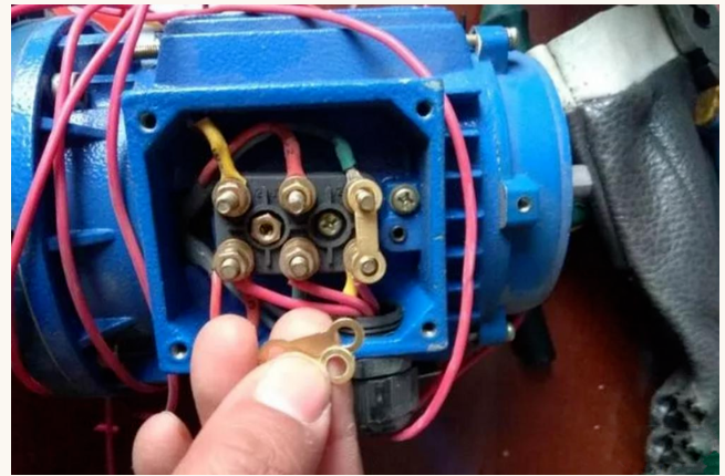
Remove these three connecting pieces when wiring.
Pay attention to the wiring of the mains section, it is best to use yellow, green and red wires.
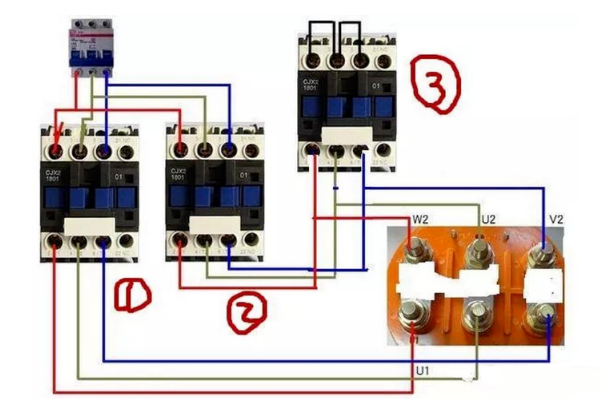
Uit die bogenoemde diagram kan ons sien dat die No.1 -kontakor en No.3 -kontakor op dieselfde tyd aanmekaar gesuig word, aangesien die boonste punt van die drie kontakters aan mekaar gekort word, die drie punte as een punt gekoppel is, hierdie een punt is gekoppel aan die motor se W2, U2, V2, wat gebeur dat dit 'n ster -verbinding is, word die neutrale punt genoem.
Star Start verminder die spanning en stroom, sodat die induksiemotor maklik begin.
Sodra dit begin is, word kontakor 3 ontkoppel, kontakor 2 word geaktiveer en Contactor 1 is die hoofkontaktor wat geaktiveer bly.
After the No. 1 and No. 2 contactors have been activated, the three windings of the motor connected become a triangular connection and the induction motor can run normally at full voltage.
Here we see the complete wiring.
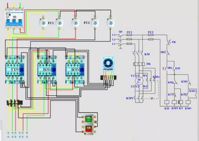
This is the complete wiring.
The thermal overload relay is connected to the mains contactor with the same phase sequence in all three phases.
The yellow, green and red diagram above shows the main line section and the black line is the secondary control line section.
Electric Motors doing star-delta starting have two important characteristics:
the star starting current and starting torque both become one third of the rated current.
The thermal overload relay is connected to the mains contactor with the same phase sequence in all three phases.
The above diagram shows the yellow-green-red main line section and the black line is the secondary line control line section.
'N Motor met 'n Star-Delta-begin het twee belangrike eienskappe: die Star Start Current en die beginwringkrag word albei een derde van die beoordeelde stroom.
Daar kan gesien word dat die stroom by die opstart baie klein is.
Star-delta starting is therefore suitable for applications where the starting torque of the motor is not strictly required, but where the starting current should be limited.
As die vrag te swaar is by die aanvang, kan dit moontlik nie die motor dra nie, aangesien die aanvangskrag tot een derde van die beoordeelde wringkrag daal, dus word 'n ster-delta-begin gebruik as die vrag lig is by die aanvang en swaar by die aanloop. As die motor-aanvangstroom te hoog is, sal dit spanningsskommelings in die rooster veroorsaak, in hierdie geval ook Star-Delta begin.
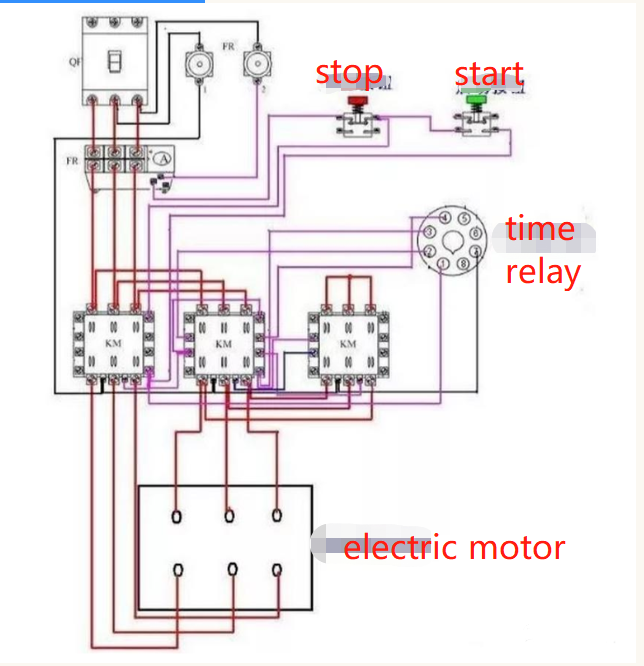
Let op die bedrading van die tyd relais in die volgende diagram.
Therefore, star-delta starter is suitable for conditions where the starting torque of the motor is not strictly required but the starting current should be limited.
Daarom is dit nie moontlik om die grootte van die motorvermoë te veralgemeen om te bepaal of die Star-Delta begin moet gebruik nie. As die vrag te swaar is wanneer dit begin, kan dit moontlik nie die motor dra nie, want die aanvangskrag daal tot een derde van die beoordeelde wringkrag, en in die algemeen word Star-Delta begin gebruik wanneer die vrag lig is wanneer dit begin en swaar is wanneer dit loop. As die motor-aanvangstroom te hoog is, sal dit skommelinge in die roosterspanning veroorsaak, in hierdie geval ook Star-Delta begin.
Let op die bedrading van die tyd -aflos, wat eenvoudig beskryf word.
To clarify these issues, we first need to review some basic electrical theory.
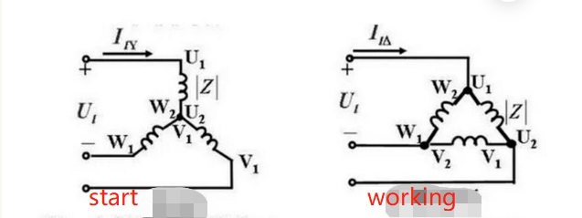
Kyk na die onderstaande diagram en laat ons begin deur die verwantskap tussen fasespanning en lynspanning, fasestroom en fasestroom vir driefase-lasstroombane in verskillende verbindingsmetodes te verstaan.
Ons weet uit die diagram dat as ons die huidige driefase-vierdraad-lae-spanning (TN) kragbronstelsel (die sogenaamde nut) gebruik wat in groot getalle in China gebruik word, wanneer die las onveranderd bly, die fasespanning aan beide ente van die las gevoeg word wanneer die sterverbinding een derde van die wortel van die lynspanning is; en die fasespanning wat aan beide ente van die las gevoeg word wanneer die hoekverbinding gelyk is aan die lynspanning.
Vir dieselfde las is die fasestroom wat deur die las vloei, gelyk aan die lynstroom as dit in die ster-modus gekoppel is, terwyl die fasestroom wat deur die las vloei 'n derde van die wortel van die lynstroom is as dit in die hoekmodus gekoppel is (wees versigtig om die verskil tussen die uitdrukking hier en die uitdrukking in die diagram hieronder te verstaan, nie verwar word nie, omdat die twee dieselfde ding beteken, slegs die uitdrukking is anders).
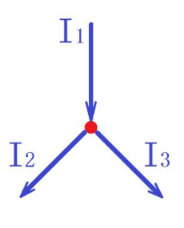
Next, let's review Kirchhoff's nodal current law, see the diagram below. From the diagram we know that the current flowing through any node is always constant equal to the current flowing out of that node [it can also be said that the algebraic sum of the currents in each branch circuit (AC is a vector sum) is equal to zero], that is, the current does not accumulate in the node
Let's take a look at the common star and angle connections of the internal windings of a three-phase squirrel-cage asynchronous motor, see the diagram below.
This is the standard connection, one of the basic knowledge that a qualified electrician must master. After understanding their principles, we can flexibly apply and maintain our equipment in future production practice, so that the equipment can serve the production better.
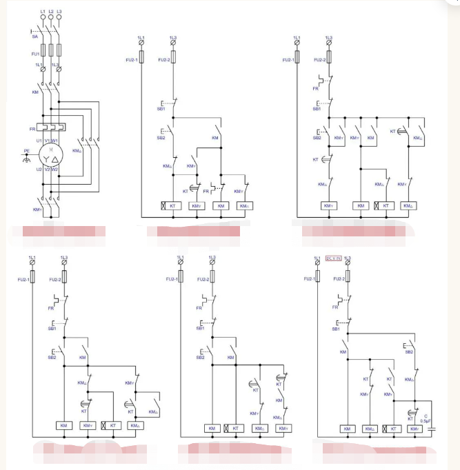
The next step is to start the analysis of the star/delta step-down starter circuit, see the diagram below.
The first main control circuit on the left in the diagram is the standard star/delta buck start main control circuit, which is a general purpose circuit.
Die eerste van die hulpbeheerkringe aan die linkerkant en die onderkant is die tradisionele standaard generiese hulpbeheerkring; Die tweede en derde is een van die hulpbeheerkringbane wat nou in die samelewing versprei; Die vierde is die hulpbeheerkring nadat ek die kring gestandaardiseer het; En die vyfde is die hulpbeheerkring nadat ek dit gestandaardiseer het.
Opmerking: die sogenaamde standaardisering is om weer te teken volgens die toepaslike standaardbepalings, nie heeltemal en deeglik volgens die standaardvereistes nie, sodat die werklading te groot is, en vir die bespreking nie nodig is nie, so lank as wat almal dit kan verstaan, verstaan dit.
Kom ons kyk eers na die Standard Star/Delta-stap-na-onder-hoofbeheerkring, wat 'n Star-af-af-begin uitmaak wanneer die KMY gesluit is. Op grond van die teoretiese bespreking van die verwantskap tussen fasespanning, lynspanning, fasestroom, lynstroom en die nodale stroomwet vroeër, weet ons dat die sterpunt wat gevorm word deur die KMY (wat na verwys kan word as die nul of neutrale punt) stroom deur die hoofkontakte van die KMY in die sterpunt sal vloei, en dat die stroom in die sterpunt gelyk is aan die lynstroom.
Aangesien die las in 'n driehoekige verbinding (in hierdie geval die driefase-wikkeling van die motor), is die spanning wat aan die ente van elke fase van die las aangebring is, die lynspanning (d.w.s. 380V), d.w.s. die fasespanning is gelyk aan die lynspanning.
As ons oorgaan na 'n sterverbinding (die las en die insetspanning bly onveranderd), is die spanning aan beide ente van elke fase van die las een derde van die wortel van die oorspronklike spanning (d.w.s. 220V), dan is die stroom wat deur elke fase van die las vloei slegs 1/3 van die oorspronklike (hoekverbinding) stroom, wat die beginsel van die begin van die spanningsvermindering is.
As the phase current of the star connection is equal to the line current, this means that the current flowing through the main contacts of the KM (main contactor) is the same as the current flowing through the main contacts of the KMY (closed star contactor). Therefore, whether or not synchronously closed or broken, the arc generated by the two contactor main contacts are the same, there is no synchronous closure of the two when the arc will be larger than the arc generated when not synchronous closure of the argument.
Therefore, as long as the correct choice (selection) and the use of qualified contactor, under normal circumstances will not appear when the contactor action due to arcing caused by contact serious ablation or adhesion of the possibility.
However, in production practice, the usual design is that KMY closes before KM. The purpose of this is to extend the service life of KMY contacts and reduce operating costs. The principle is that the KM is selected according to the angular operating current, while the KMY is selected according to the star connection current. If the KMY closes before the KM, there will be no start-up arcing (there will still be when the star/angle switch is broken), so that the arcing at start-up is borne by the KM with higher specifications than the KMY, which is much better than the KMY with lower specifications.
If the design of KMY in the star/angle switch first disconnect KM and then disconnect KMY best (because the arc when breaking than when closed much larger arc), but this will cause the auxiliary control circuit structure complexity and economic cost increases, sometimes more than worth the loss.
Look again at the KM△ angular connection contactor. As the angle connection when the current flowing through the KM△ main contact is the phase current, equal to the root of the line current 3 parts, generally speaking, in order to be safe and reliable, is selected according to the line current.
This is because the arc may be larger during the conversion process and may easily burn the contactor contacts. Of course, if KM△ is closed before KM, KM△ can be selected according to the phase current (one third of the root number of the line current).
But this will make the control circuit structure complex, equipment manufacturing costs not only did not come down, it is not good enough to make more losses than gains.
The analysis of the main circuit of the star/delta buck start summary: as long as the correct choice of the type of contactor specifications and qualified products, under normal circumstances contactor contact ablation should not be a problem, that KM and KMY synchronous action will cause arcing is a misunderstanding.
In werklikheid is daar baie redes vir die boog, maar die belangrikste is dat die omskakelingstyd van die ster/hoek nie behoorlik ingestel is nie, of dat die las te swaar is.
Die begintyd is nie genoeg om te vroeg te omskep nie; Sommige is die kwaliteit van die motor self, of die gewone onderhoud is nie genoeg nie; die lopende stroom word groot; Sommige is die motor wat met siektes of onredelike ontwerp loop, wat lei tot langtermyn-oorbelastingwerking van die motor wat veroorsaak word, natuurlik nie die ontwerp of die tipe, spesifikasie en kwaliteit van die kontakor wat in die instandhoudingsproses gebruik word, nie aan die vereistes voldoen nie.
Let ook daarop dat Star/Delta Spanning Reduction begin 'n sekere toepassingsreeks het, en nie noodwendig beter is as ander beginmetodes vir die vermindering van spanning nie. Aangesien die aanvangstroom van Star/Delta-spanningvermindering 1/3 van die volspanning-aanvangstroom is, is die beginwringkrag slegs 1/3 van die oorspronklike aanvangskrag, wat slegs van toepassing is op ligte of geen-laai-toerusting (toerusting soos pompe of lugkompressors, moet die inlaat-/uitlaatklep of die voorgepaste lugtenk afsluit voordat die Star/Delta-spanningsvermindering van die voorsprong van die motor afgesluit word).
Vir sterk gelaaide aanvangstoerusting het die begintye van meer as 30 sekondes (veral meer as 1 minuut) 'n beduidende impak op die motor en die toevoerlyn (veral as die aanbodtransformator onder kapasiteit is).
Hoe swaarder die las (of hoe hoër die krag) die motor, die ander beginmetodes [bv. AutoTransfer Buck Start, uitgebreide sykant -driehoek Buck Start, Stator Series Reactor (of weerstand) Buck Start, Soft Starter Buck Start, Frequency Converter Inverter Start, ens.] Moet gebruik word om die beginmetode volgens die spesifieke werklike situasie te kies.
Daarom is dit 'n wanopvatting om te dink dat die begin van Star/Delta Buck baie beter is as ander metodes vir die begin van die bok;
It is also a mistake to think that no matter what equipment is used, as long as buck starting is used, all star/delta buck starting methods are used (the advantage of star/delta buck starting is its simple structure and small size).
The following is a discussion of the auxiliary control circuit for star/delta buck starting.
Die hulpbeheerstroombaan, wat na die beheerkring verwys word, is 'n stroombaan wat die voorwerp wat volgens die prosesvereistes beheer word, beheer. Van die vyf beheermetodes hierbo getoon, is die beheermetodes baie dieselfde, behalwe vir die vierde, wat slegs in kringkonstruksie verskil, waarvan die vierde die teenoorgestelde van die eerste drie is, en die laaste is die toevoeging van 'n hoekvertragingsfunksie vir hoekskakelaar tot die eerste drie beheerkringbane.
Die eerste beheerkring is die tradisionele, standaardbeheerkring, wat die eerste verseëlde ster (KMY) is voordat die hoofkontaktor (km) sluit om die hoofstroombaan met 'n bokstuik te voorsien, en na die begin is die volledige draai na hoekbewerking en die werking van die tyd relaisuitgang.
This circuit has a simple circuit structure yet meets the characteristics of safe and reliable operation.
The second and third control circuits are similar to the first control circuit in that they both seal the star first before supplying a step-down start, and the time relay exits after the start is complete.
The difference is that the circuit structure is a little more complex, adding some double chain contacts, with more safety and reliability than the first control circuit.
In particular, the second control circuit, the contacts used the most, although the safety and reliability increased a lot, but also a lot more difficult to maintain.
The fourth is a designed circuit. For this circuit, I personally think that it is not very reasonable and perfect.
Although the double chain function is added, the main contactor KM closes before the sealing star contactor KMY, and the sealing star contactor KMY often operates under arcing, which is always better than sealing the star first and then energising the buck start.
Although harmless, but compared to the first seal star, after the seal star so that the contactor KMY contacts are always much shorter than the first seal star contact life (more than double the work with arc light).
The long-term involvement of the time relay KT in operation is a hard part of this circuit.
As we know, the life of a component that is constantly energised and involved in operation is much shorter than if it is not, and the power consumption increases.
As the saying goes, "more incense burners, more ghosts", your time relay KT is involved in long-term operation, so it may give you a failure in operation at some point, affecting the efficiency of the equipment and increasing operating and maintenance costs.
The fifth is the circuit provided.
Although in the operation of the action and the previous three similar, with the first sealed star after the power and time relay is not involved in the operation of the function, but the use of parallel capacitor C to extend the angle contactor KM△ closure is a bit of a snake - redundant.
And the delay function only in the DC supply control circuit to play a role in the AC circuit, but no role, or even a redundant and cumbersome thing.
You don't know when to give you a breakdown or leakage caused by a fault.
Be aware that the reverse peak voltage of an inductor in a DC circuit is four to five times more than the rated voltage.
Well, that's it for the analysis of star/delta buck starting circuits.
Welcome to leave a message in the comments area for any information.
Kontak die professionele elektriese motor enige ondersoek na elektriese motor vervaardiger in Sjina soos volg:

Dongchun Motor het 'n wye verskeidenheid elektriese motors wat in verskillende industrieë gebruik word, soos vervoer, infrastruktuur en konstruksie.
Kry 'n vinnige antwoord.


